Monitoring motor speed
The initial idea was to connect moteino's digital input on the three wire connecting the motor to the speed controller. Then, because I sensed that the community of rc drivers were reluctant to the idea of interfering with the precious signal coming from the expensive controller, I though that the “sensored” connector might be a good option.
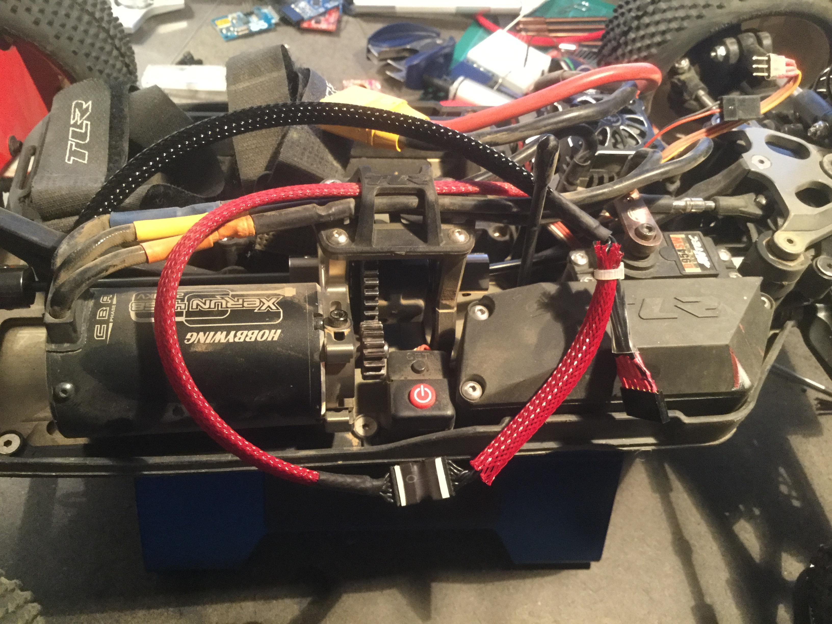
Looking at its specification, I realised that not only I could get the same result but also that the controller powers to PCB inside the motor with 5V (just what we need to power the moteino) but also that the motor was equipped with a small thermistor that I could use to read motor temperature.
Connecting the oscilloscope to wires 2, 3 and 4 showed three beautiful digital signals send by the three HAL sensors inside the motor.
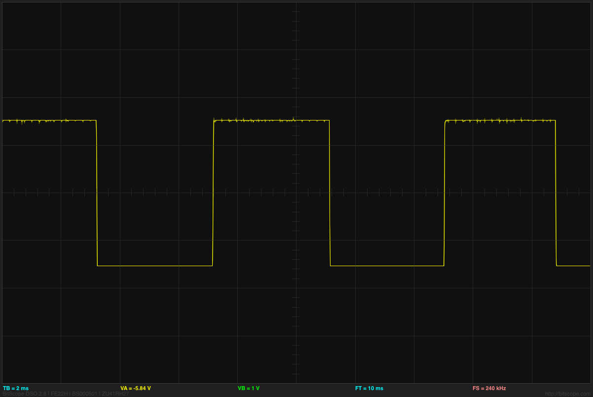
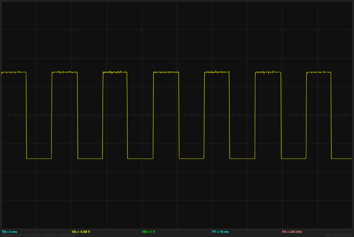
A bit of wiring later, the moteino was mounted on the “sensored” line. I used the PinChangedInterupt library to detect the square signals on each wires and calculate the RPM. I used interrupt to make sure I dont miss a signal while sending over the RFM69. When pushed to the max, the motor shows 120000 RPM which I divided by two to obtain the 60000RPM that I expect considering the 4S and the 2250kvm motor but I should investigate further more to understand exactly why. I guess rotating the axe of the motor manually and see which HAL sensor turn low and when will help.